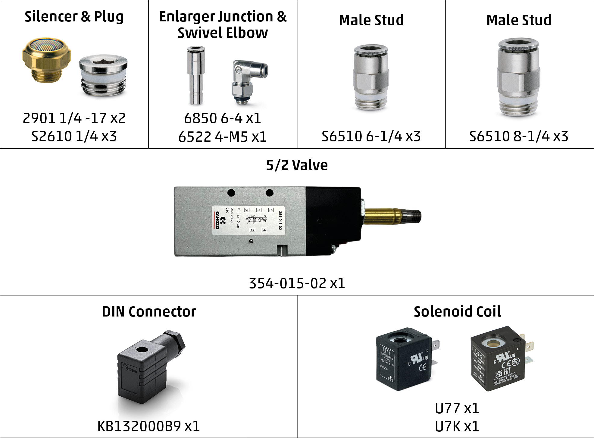
What's in the Box
Identifying Ports
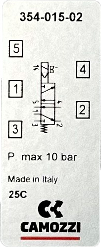
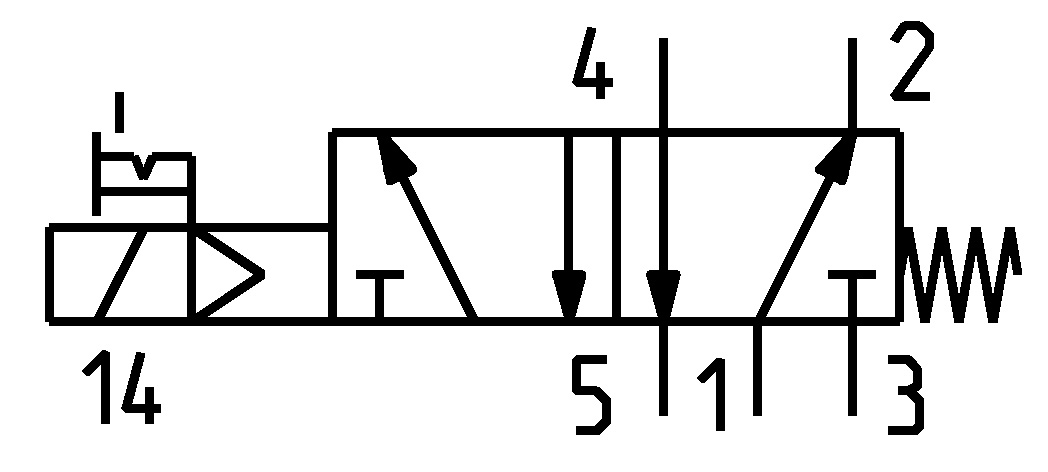
On the front of the 354-015-02 valve, there is a label indicating the port numbers. This label is also displayed below for your reference. Additionally, an enlarged technical drawing is provided to help you accurately identify the correct ports.
1. 2/2 Normally Closed (N/C) Solenoid/Spring Valve
Instructions
- Attach the Solenoid Coil:
- Take the U7* solenoid coil and place it over the solenoid operator on the 354-015-02 valve.
- Secure it in place using the provided screw.
- Connect the Solenoid Connector:
- Align the KB132000B9 solenoid connector with the prongs on the U7* coil.
- Slot the connector onto the prongs and secure it using the small screw provided.
- Port Connections:
- Locate Port 1 on the valve. Choose the appropriate S6510 fitting (6mm or 8mm) and screw it into Port 1.
- Repeat this step for Port 4 using another S6510 fitting (6mm or 8mm).
- Insert S2610 blanking plugs into Ports 2, 3, and 5.
2. 2/2 Normally Open (N/O) Solenoid/Spring Valve
Instructions
- Attach the Solenoid Coil:
- Take the U7* solenoid coil and place it over the solenoid operator on the 354-015-02 valve.
- Secure it in place using the provided screw.
- Connect the Solenoid Connector:
- Align the KB132000B9 solenoid connector with the prongs on the U7* coil.
- Slot the connector onto the prongs and secure it using the small screw provided.
- Port Connections:
- Locate Port 1 on the valve. Choose the appropriate S6510 fitting (6mm or 8mm) and screw it into Port 1.
- Repeat this step for Port 2 using another S6510 fitting (6mm or 8mm).
- Insert S2610 blanking plugs into Ports 3, 4, and 5.
3. 3/2 Normally Closed (N/C) Solenoid/Spring Valve
Instructions
- Attach the Solenoid Coil:
- Take the U7* solenoid coil and place it over the solenoid operator on the 354-015-02 valve.
- Secure it in place using the provided screw.
- Connect the Solenoid Connector:
- Align the KB132000B9 solenoid connector with the prongs on the U7* coil.
- Slot the connector onto the prongs and secure it using the small screw provided.
- Port Connections:
- Locate Port 1 on the valve. Choose the appropriate S6510 fitting (6mm or 8mm) and screw it into Port 1.
- Insert S2610 blanking plugs into Ports 2 and 3.
- Locate Port 4 and screw in another S6510 fitting (6mm or 8mm).
- Insert the 2901 1/4-17 silencer into Port 5.
4. 3/2 Normally Open (N/O) Solenoid/Spring Valve
Instructions
- Attach the Solenoid Coil:
- Take the U7* solenoid coil and place it over the solenoid operator on the 354-015-02 valve.
- Secure it in place using the provided screw.
- Connect the Solenoid Connector:
- Align the KB132000B9 solenoid connector with the prongs on the U7* coil.
- Slot the connector onto the prongs and secure it using the small screw provided.
- Port Connections:
- Locate Port 1 on the valve. Choose the appropriate S6510 fitting (6mm or 8mm) and screw it into Port 1.
- Repeat this step for Port 2 using another S6510 fitting (6mm or 8mm).
- Insert the 2901 1/4-17 silencer into Port 3.
- Insert S2610 blanking plugs into Ports 4 and 5.
5. 5/2 Solenoid/Spring Valve
Instructions
- Attach the Solenoid Coil:
- Take the U7* solenoid coil and place it over the solenoid operator on the 354-015-02 valve.
- Secure it in place using the provided screw.
- Connect the Solenoid Connector:
- Align the KB132000B9 solenoid connector with the prongs on the U7* coil.
- Slot the connector onto the prongs and secure it using the small screw provided.
- Port Connections:
- Locate Port 1 on the valve. Choose the appropriate S6510 fitting (6mm or 8mm) and screw it into Port 1.
- Repeat this step for Port 2 using another S6510 fitting (6mm or 8mm).
- Insert the 2901 1/4-17 silencer into Port 3.
- Repeat the S6510 fitting step for Port 4 (6mm or 8mm).
- Insert another 2901 1/4-17 silencer into Port 5.
6. 2/2 Normally Closed (N/C) Pilot/Spring Valve
Instructions
- Port Connections:
- Locate Port 1 on the valve. Choose the appropriate S6510 fitting (6mm or 8mm) and screw it into Port 1.
- Insert S2610 blanking plugs into Ports 2 and 3.
- Locate Port 4 and screw in another S6510 fitting (6mm or 8mm).
- Insert S2610 blanking plug into Port 5.
- Attach the Coil Stem:
- Take the 6522 4-M5 coil stem and attach it to the valve.
7. 2/2 Normally Open (N/O) Pilot/Spring Valve
Instructions
- Port Connections:
- Locate Port 1 on the valve. Choose the appropriate S6510 fitting (6mm or 8mm) and screw it into Port 1.
- Repeat this step for Port 2 using another S6510 fitting (6mm or 8mm).
- Insert S2610 blanking plugs into Ports 3, 4, and 5.
- Attach the Coil Stem:
- Take the 6522 4-M5 coil stem and attach it to the valve.
8. 3/2 Normally Closed (N/C) Pilot/Spring Valve
Instructions
- Port Connections:
- Locate Port 1 on the valve. Choose the appropriate S6510 fitting (6mm or 8mm) and screw it into Port 1.
- Insert S2610 blanking plugs into Ports 2 and 3.
- Locate Port 4 and screw in another S6510 fitting (6mm or 8mm).
- Insert the 2901 1/4-17 silencer into Port 5.
- Attach the Coil Stem:
- Take the 6522 4-M5 coil stem and attach it to the valve.
9. 3/2 Normally Open (N/O) Pilot/Spring Valve
Instructions
- Port Connections:
- Locate Port 1 on the valve. Choose the appropriate S6510 fitting (6mm or 8mm) and screw it into Port 1.
- Repeat this step for Port 2 using another S6510 fitting (6mm or 8mm).
- Insert the 2901 1/4-17 silencer into Port 3.
- Insert S2610 blanking plugs into Ports 4 and 5.
- Attach the Coil Stem:
- Take the 6522 4-M5 coil stem and attach it to the valve.
10. 5/2 Pilot/Spring Valve
Instructions
- Port Connections:
- Locate Port 1 on the valve. Choose the appropriate S6510 fitting (6mm or 8mm) and screw it into Port 1.
- Repeat this step for Port 2 using another S6510 fitting (6mm or 8mm).
- Insert the 2901 1/4-17 silencer into Port 3.
- Repeat the S6510 fitting step for Port 4 (6mm or 8mm).
- Insert another 2901 1/4-17 silencer into Port 5.
- Attach the Coil Stem:
- Take the 6522 4-M5 coil stem and attach it to the valve.